Home | 21c mic | nfc mic kit
NFC Microphone Kit ("21c lite" v2024)
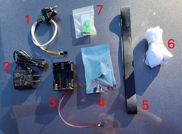
Parts excluding mic attachment.
INTRODUCTION
This is a DIY microphone for tuning into avian nocturnal flight calls (nfcs). The improvement from the former Old Bird DIY design is in the simplicity of construction (no soldering), the fact that the electronics are supplied in the kit, and that it has much better functionality for detecting nfcs (better signal to noise ratio). Like the old design, the user is responsible for obtaining the microphone housing & audio cable, and building the microphone. Once the parts are in hand, construction takes about half an hour.
PARTS
Kit includes the following parts (shown above):
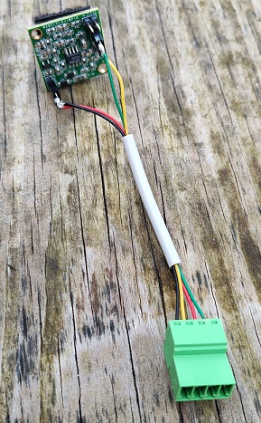
1. Cable for connecting circuit board to the audio recorder and power supply.
2. AC to 12V DC power supply.
3. 6 x AA battery holder for off-grid operation.
4. Preamp circuit board and spare mic capsule w/leads.
5. Rubber band for holding nylon cover in place over opening of exterior mic housing (e.g., 1 or 2-gallon plastic bucket)
6. Translucent nylon fabric for exterior mic housing cover.
7. Solderless 4-wire connector to join user-acquired length of cable to the short wire inside interior mic housing.
8. 4-sided acrylic pyramid with mounted PUI AOM mic capsule.
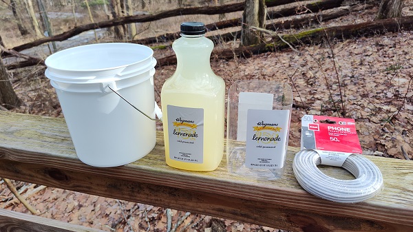
Suggested parts for user to acquire (<$20 USD):
1. ~1-gallon paint bucket or similar (recommend white or light color to minimize heat absorbtion; e.g., Leaktite 1-gal white pail.
2. ~1.25 quart tall juice container or similar. If possible, get a four-sided version like the one shown in the pic below.
3. Wire for transmitting signal. 4-conductor round telephone wire is durable & economical for outdoor use. If not available in a local hardware store, it can be ordered online. Any 4-conductor cable will work. If the cable used has different colors than the green, red, yellow, and black noted in these instructions, just remember which color is used in replacement.
click to enlarge
CONSTRUCTION
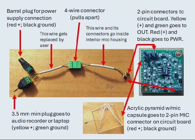
Step 1: The circuit board has three 2-pin male connectors, each inscribed with its function and a + sign by one of the pins. The 2-pin PWR port receives power from the battery pack (for off-grid operation) or the 2-pin connector carrying power from an AC to 12VDC wall plug (or other 12V source). The OUT port receives the 2-pin female connector from the signal out cable, which connects to the audio cable running to the listening/recording station. That cable can carry power in its red (+) and black (ground) wires and the audio signal in its yellow (+) and green (return) wires. Be careful with the 2-pin connectors as they are delicate and repeated bending may result in the wires breaking and needing to be resoldered.
click to enlarge
Step 2: Preparation of containers: Drink the juice out of juice container, rinse well, and cut off top third that tapers to the spout. Drill four 1/5 inch holes in the bottom and one about half way up one of the sides. For the 1-gallon bucket, drill three ~1/4 inch drain holes in the bottom and one 2 to 3 inches up from the base. Note: If a drill isn't available, and exacto or other sharp knife will work for making the holes.
Step 3: Select the length of cable to be used for transfering the audio signal from the microphone to recording device. Run one end of it into the bucket, out the top, and into the modified container. Strip an inch of the plastic cover off the end of the cable and a quarter inch off the end of the four wires within. Unscrew the openings of one half of the green wire to wire connector (part #7). Insert the four wires into the holes and then screw each tight in place. Put a small square of velcro on the inside of the juice container housing adjacent to the hole where the cable comes in.
click to enlarge
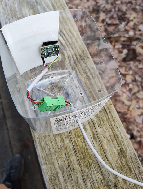
Put a 1 inch x 1 inch square of velcro on the inside of the juice container housing adjacent to the hole where the cable comes in. Put an opposite velcro piece on the back of the circuit board. Connect the short wire with the 2-pin connectors to their appropriate 2-pin male connector on the circuit board. Red and black wired 2-pin female goes to the PWR port (red to the + side); yellow and green wired 2-pin female goes to the OUT port (yellow to the + side). Now align and attach the two velco piece so that the MIC connector pins are at the top, and at the other end connect to two green connector pieces.
click to enlarge
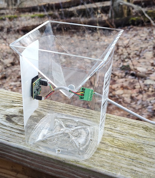
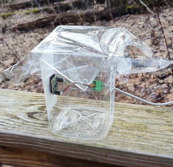
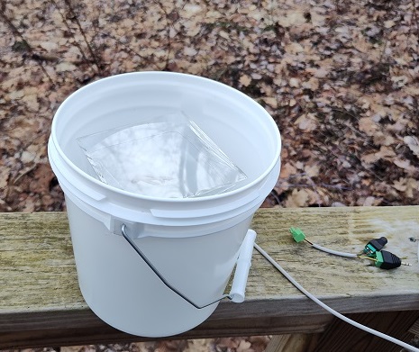
Step 3: Connect the 2-pin connector coming from the acrylic pyramix the MIC port on the circuit board (red wire to +). Next, drape a piece of plastic food wrap over the pyramid so that it hangs about an inch down onto one of the sides of the container. Tape one side of th plastic wrap to the side of container, and then on the opposite side pull the wrap taught and tape that side down (may need to trim it off so only an inch or so hangs down below the top of the container. Continue with the other two sides being careful not to stretch the wrap, just pull it taught. The idea is to form a taught waterproof membrane over the top of the pyramid so as to prevent water from entering the chamber of the container in order to protect the electronics.

Click to enlarge
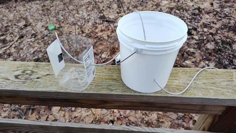
Step 4: Append 1 inch squares of velcrow to the bottom of the four corners of the container. Put corresponding opposite velcrow pieces centered in the bottom of the bucket. Place container into the bucket so the velcrow pieces connect, then pull the slack of the cable outside the bucket until cable loop stops it.
click to enlarge
Step 5: Drape a piece of thin nylon cloth (e.g., translucent curtain) over the mouth of the bucket and secure in place with rubberband and trim off excess cloth.
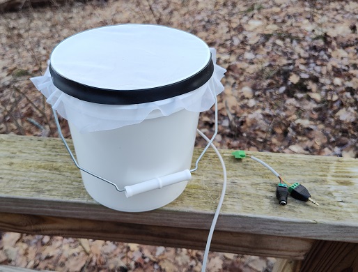
click to enlarge
Step 6: Finally, at the listening/recording station end of the audio cable, strip the plastic cover off latter 1/4 inch of the four wires in the interior of the cable. Connect the red & black (or corresponding colored) wires to the barrel plug terminal connector (red to +; black to ground). Connect the yellow & green (or corresponding colored) wires to the miniplug terminal connector (yellow to L or leftmost port; green to ground or rightmost port). The mic is now ready to test!
Home | 21c mic | NFC mic kit