| Home | old mic design and building instructions
2020 NFC DIY Microphone Kit ("21c lite")
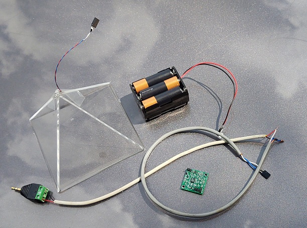
All parts shown above are included except the batteries and the white cable. The user supplies the batteries (6 x AA) and the length of cable needed for their listening/recording station.
INTRODUCTION
This is a DIY microphone system for tuning into avian nocturnal flight calls (nfcs). The improvement from the former Old Bird DIY design is in the simplicity of construction (no soldering), the fact that most fundamental parts are supplied in the kit, and that it has much better functionality for detecting nfcs (better signal to noise ratio). While the $125 cost is a more expensive than the circa 2000 home-made design, the kit includes the preamp - formerly one had to acquire the preamp separately. Like the old design, the user is responsible for obtaining the microphone housing & audio cable, and building the microphone. Once the parts are in hand, construction takes about half an hour.
PARTS
The kit includes the following parts (shown above):
Microphone element mounted in acrylic pyramid
Preamp circuit board
Battery connector cable with housing for 6 AA batteries (not included), which power mic for 3-4 months
Signal out connector cable (gray cable above)
Terminal-block 3.5 mm (1/8 in) miniplug connector
Screws & electrical connection caps
Suggested parts for user to acquire:
~2-gallon paint bucket or similar (recommend white or light color to minimize heat absorbtion; e.g., Lowe's Item #954439)
~32 oz. tall container or similar (e.g., typical large yogurt container)
Wire for transmitting signal. 2-conductor is needed for mono. 4-conductor round telephone wire from Lowe's is durable & economical for outdoor use (Item #303015; #303007) - for one microphone, just use the black and red conductors for ground and signal respectively.
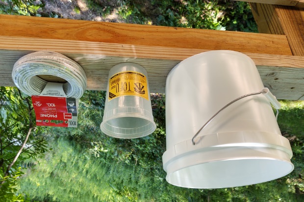
Examples of accessories to use in building DIY microphone - white 2-gallon plastic bucket, 32 oz plastic container, telephone wire.
CONSTRUCTION
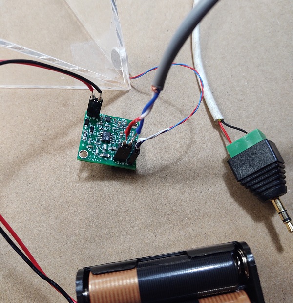
Step 1: Before inserting circuitry into containers, review how the circuit board and wires are to be connected in the picture below. The circuit board has three 2-pin male connectors, each inscribed with its function and + sign by one of the pins. The PWR port receives the 2-pin female from the battery pack, the MIC port receives the 2-pin female connector from the mic element mounted in the pyramid, and the OUT port receives the 2-pin female connector from the signal out cable, which connects to the audio cable running to the listening/recording station. The reds wire in all three 2-pin female connectors goes to the + terminal of the male 2-pin connector on the circuit board. Be careful with the 2-pin connectors as they are delicate and repeated bending may result in the wires breaking.
Step 2: Mount the circuit board in the small plastic container ~ 3+ inches up from the bottom. Orient the circuit board so that the 2-pin PWR connector is on the low side. Once the circuit board is mounted,